Difference between revisions of "OptiTUIO Manual"
(→TUIO output) |
(→Supported LIDAR sensors) |
||
| (64 intermediate revisions by the same user not shown) | |||
| Line 1: | Line 1: | ||
==Introduction== | ==Introduction== | ||
| − | [[File:OptiTUIO big website.jpg|600px]] | + | <center>[[File:OptiTUIO big website.jpg|600px]]</center> |
{{Ot}} is a tool to calibrate optical LIDAR sensor devices. With {{ot}} it is possible to use laser contour scanners like the Leuze ROD4plus, Hokuyo sensors or the Sick LMS models for controlling any number of applications. | {{Ot}} is a tool to calibrate optical LIDAR sensor devices. With {{ot}} it is possible to use laser contour scanners like the Leuze ROD4plus, Hokuyo sensors or the Sick LMS models for controlling any number of applications. | ||
| Line 29: | Line 29: | ||
** Chinese | ** Chinese | ||
** French | ** French | ||
| + | ** Arabic | ||
| + | ** Portuguese | ||
| + | ** Spanish | ||
| + | ** Thai | ||
We will translate the software into more languages if there is the need. | We will translate the software into more languages if there is the need. | ||
| Line 55: | Line 59: | ||
===Supported LIDAR sensors=== | ===Supported LIDAR sensors=== | ||
| + | * Hokuyo UST-10LX H01 | ||
| + | * Hokuyo UST-10LX H01 | ||
* Hokuyo UST-10LX | * Hokuyo UST-10LX | ||
* Hokuyo UST-20LX | * Hokuyo UST-20LX | ||
| Line 62: | Line 68: | ||
* Sick LMS 1xx series | * Sick LMS 1xx series | ||
* Sick LMS 5xx series | * Sick LMS 5xx series | ||
| + | |||
| + | |||
| + | Please check this table for the features and specifications of the supported LIDAR sensors. | ||
| + | |||
| + | {|class="wikitable" | ||
| + | ! style="text-align:left;"| Sensor | ||
| + | !Hokuyo | ||
| + | !Hokuyo | ||
| + | !Hokuyo | ||
| + | !Hokuyo | ||
| + | !Hokuyo | ||
| + | !Sick | ||
| + | !Sick | ||
| + | !Leuze | ||
| + | |- | ||
| + | |'''Model''' | ||
| + | |UST-10LX H01 | ||
| + | |UST-20LX H01 | ||
| + | |UST-10LX | ||
| + | |UST-20LX | ||
| + | |URG-04LX UG04 | ||
| + | |LMS 1xx | ||
| + | |LMS 5xx | ||
| + | |Leuze ROD4 plus | ||
| + | |- | ||
| + | |'''Accuracy''' | ||
| + | |±20mm | ||
| + | |±20mm | ||
| + | |±30mm | ||
| + | |±30mm | ||
| + | |±30mm | ||
| + | |±25mm | ||
| + | |±25mm | ||
| + | |N.A. | ||
| + | |- | ||
| + | |'''Measuring area''' | ||
| + | |270° | ||
| + | |270° | ||
| + | |270° | ||
| + | |270° | ||
| + | |240° | ||
| + | |270° | ||
| + | |190° | ||
| + | |190° | ||
| + | |- | ||
| + | |'''Angular resolution''' | ||
| + | |0.125° | ||
| + | |0.125° | ||
| + | |0.25° | ||
| + | |0.25° | ||
| + | |0.36° | ||
| + | |0.25°/0.5° | ||
| + | |0.166°/1° | ||
| + | |0.36° | ||
| + | |- | ||
| + | |'''Scan rate''' | ||
| + | |40Hz | ||
| + | |40Hz | ||
| + | |40Hz | ||
| + | |40Hz | ||
| + | |10Hz | ||
| + | |25Hz/50Hz | ||
| + | |25Hz - 100Hz | ||
| + | |25Hz/50Hz | ||
| + | |- | ||
| + | |'''Scan Range''' | ||
| + | |10m | ||
| + | |20m | ||
| + | |10m | ||
| + | |20m | ||
| + | |3m | ||
| + | |20m | ||
| + | |30m | ||
| + | |15m | ||
| + | |- | ||
| + | |'''Connection''' | ||
| + | |Ethernet | ||
| + | |Ethernet | ||
| + | |Ethernet | ||
| + | |Ethernet | ||
| + | |USB | ||
| + | |Ethernet | ||
| + | |Ethernet | ||
| + | |Ethernet | ||
| + | |- | ||
| + | |'''Outdoor''' | ||
| + | |No | ||
| + | |No | ||
| + | |No | ||
| + | |No | ||
| + | |No | ||
| + | |Yes | ||
| + | |Yes | ||
| + | |Yes | ||
| + | |- | ||
| + | |'''Multi Echo Filter''' | ||
| + | |No | ||
| + | |No | ||
| + | |No | ||
| + | |No | ||
| + | |No | ||
| + | |Yes | ||
| + | |Yes | ||
| + | |Yes | ||
| + | |- | ||
| + | |'''Ambient light''' | ||
| + | |15000lx | ||
| + | |15000lx | ||
| + | |15000lx | ||
| + | |15000lx | ||
| + | |10000lx | ||
| + | |40000lx | ||
| + | |70000lx | ||
| + | |Sunlight | ||
| + | |- | ||
| + | |'''Enclosure rating''' | ||
| + | |IP65 | ||
| + | |IP65 | ||
| + | |IP65 | ||
| + | |IP65 | ||
| + | |none | ||
| + | |IP65/IP67 | ||
| + | |IP65/IP67 | ||
| + | |IP65 | ||
| + | |} | ||
| Line 100: | Line 231: | ||
* ''vcredist_x64.exe'' (Visual C++ runtime) | * ''vcredist_x64.exe'' (Visual C++ runtime) | ||
| − | {{ | + | {{Infotext|We suggest to run the software during shows with the server application. After you saved the calibration with the calibration application just start the server application and choose the saved calibration file.}} |
| + | |||
| + | Find more infos here how to [[https://wiki.interactive-asia.com/index.php?title=Manual#Autostart_the_server Autostart the server]] | ||
===MacOS=== | ===MacOS=== | ||
| Line 132: | Line 265: | ||
The Graphical User Interface of {{ot}} will start | The Graphical User Interface of {{ot}} will start | ||
| + | |||
| + | In the main menu you can find the typical menu entries: | ||
| + | |||
| + | * '''File''' - To load configuration files, save configuration files and exit the application | ||
| + | * '''View''' - To customize the preview window and open the Log window. | ||
| + | * '''Help''' - To install the license and view the license details. | ||
[[File:Gui01.png|700px|Thsi window will appear when you start OptiTUIO]] | [[File:Gui01.png|700px|Thsi window will appear when you start OptiTUIO]] | ||
| + | |||
| + | |||
| + | * '''Language''' - Change the User Interface to your desired language | ||
| + | * '''Max. tracking distance''' - This value specifies from which distance to an existing touch point a new touch point is detected or if it is an existing one. Normal values are between 100mm - 400mm | ||
| + | * '''Merge distance''' - This value specifies the distance from which two touch points get merged together into one. Very helpful when applications are controlled with fingers on short distances, for example. Standard value is 40mm. | ||
| + | |||
| Line 173: | Line 318: | ||
{{WarningText|The demo license is not for commercial use. It is for testing purpose only!}} | {{WarningText|The demo license is not for commercial use. It is for testing purpose only!}} | ||
| − | |||
{{infotext|You can install the license on any machine and Operating system which is supported by OptiTUIO.}} | {{infotext|You can install the license on any machine and Operating system which is supported by OptiTUIO.}} | ||
| Line 186: | Line 330: | ||
{{infotext|The Hokuyo UST 10 LX, Hokuyo UST 20LX and the Hokuyo URG04 can be added via the Hokuyo URG item. This item includes all the Hokuyo sensors.}} | {{infotext|The Hokuyo UST 10 LX, Hokuyo UST 20LX and the Hokuyo URG04 can be added via the Hokuyo URG item. This item includes all the Hokuyo sensors.}} | ||
| + | |||
| + | |||
| + | |||
| + | |||
===Settings of the sensor=== | ===Settings of the sensor=== | ||
| Line 199: | Line 347: | ||
This is the control panel to add, remove, start and stop the sensor. | This is the control panel to add, remove, start and stop the sensor. | ||
| − | [[File: | + | [[File:OptituioAdvanced.png|700px]] |
| − | |||
| − | |||
| − | |||
| − | |||
| − | |||
| − | |||
| + | * '''Add''' - this button opens the available sensor list where you can choose your sensor | ||
| + | * '''Remove''' - this button removes the selected sensor | ||
| + | * '''Start''' - Starts the sensor and the sensor will start scanning. If the sensor is runnig you can see the blue scanning area in the sensor view window | ||
| + | * '''Stop''' - Stops a running sensor and the sensor will stop scanning | ||
| + | * '''Info''' - This button shows you the serial number of the connected sensor. This button just works if the sensor is not running and connected correctly. | ||
| + | * '''Advanced''' - opens a new window where you can access [[https://wiki.interactive-asia.com/index.php?title=OptiTUIO_Manual#Advanced_Settings Advanced Setting]] | ||
{{Infotext|If you connected a sensor you can read out the serial number of the connected sensor via the ''Info button''}} | {{Infotext|If you connected a sensor you can read out the serial number of the connected sensor via the ''Info button''}} | ||
| Line 229: | Line 377: | ||
{{WarningText|If you have not assigned the screen under the ''Devices'' tab you will not get any touch output}} | {{WarningText|If you have not assigned the screen under the ''Devices'' tab you will not get any touch output}} | ||
| + | |||
| + | ====Advanced Settings==== | ||
| + | |||
| + | |||
| + | |||
| + | This feature is new since release ''OptiTUIO V1.2.3'' | ||
| + | |||
| + | |||
| + | In this tab you have access to some advanced features. | ||
| + | |||
| + | [[File:OptituioAdvanced03.png]] | ||
| + | |||
| + | |||
| + | {{WarningText|This values are just exposed for our developers and some special cases. They should not be changed for normal usage}} | ||
| + | |||
| + | * '''Bilateral filter''' - For some special setups, especially when there are some error close to the sensor you can try to turn this option on. (default = off (unchecked)) | ||
| + | |||
| + | * '''Margin''' - in some special cases you can adjust the margin that the touches are also recognized a bit outside of the actual touch area. | ||
| + | |||
| + | * '''Max. touch deviation''' - This is a very specific value and should not be changed!!! | ||
| + | |||
| + | * '''Min. touch segments''' - Defines how many rays have to recognize a object until its recognized as a touch point (default = 3) | ||
| + | |||
| + | * '''Min. touch age''' - The age of a touch point in frames before he gets sent to the output. | ||
| + | |||
| + | * '''Record''' button - Here you can record a file of the tracking process to send it to us for troubleshooting issues | ||
===Start the sensor=== | ===Start the sensor=== | ||
| Line 242: | Line 416: | ||
# Once the sensor is started you can see the blue scan area in the sensor view. | # Once the sensor is started you can see the blue scan area in the sensor view. | ||
# In the bottom left corner of the GUI you can also see the scanning frequency of the sensor. | # In the bottom left corner of the GUI you can also see the scanning frequency of the sensor. | ||
| + | |||
| + | |||
| + | {{Infotext|Make sure that your network configurations are setup correctly. Find more info's here [[Hardware / Networking]]}} | ||
===Setup the screen=== | ===Setup the screen=== | ||
| Line 281: | Line 458: | ||
====Mouse output==== | ====Mouse output==== | ||
| + | |||
| + | The mouse is the primary input device used to interact with objects in Windows, Linux and MacOS. This output will simply control your mouse pointer. There are two different control options with the windows mouse. | ||
| + | |||
| + | The following list describes the settings of the Mouse output. | ||
| + | |||
| + | * Name - Here you can assign a name for your output | ||
| + | * Offset X - Here you can offset your mouse pointer in X direction. | ||
| + | * Offset Y - Here you can offset your mouse pointer in Y direction. | ||
| + | * Size X - This value is set automatically if you start {{ot}}. It is the width in pixel of the screens you have connected to your computer. You can change this values if you just want to control one screen. | ||
| + | * Size Y - This value is set automatically if you start {{ot}}. It is the height in pixel of the screen you have connected to your computer. | ||
| + | * Screen - If you have more then one screen then you can define from which screen the Mouse information's will come (default: All) | ||
| + | * Mode - ''Simple'' and ''Two click''. | ||
| + | **The simple mode uses the first touch point and moves the mouse directly to that position and executes a left click. | ||
| + | **The two click mode uses the first touch point to move the mouse pointer without any click action. If you hold your first finger in the screen then you can create a Left click if you touch with your other hand left side of the first hand. Or a right click if you touch right side of your first hand which controls the point. | ||
| + | |||
| + | {{Infotext|The mouse just can be controlled with one touch point. Or in the two click mode with maximum two touch points. There is no way to control two mouse pointers with one OS.}} | ||
====Windows touch output==== | ====Windows touch output==== | ||
| + | |||
| + | New hardware and API elements in the Windows 7 operating system provide applications the ability to receive input from multiple contacts. This gives such applications the ability to detect and respond to multiple simultaneous touch points on the application's visible surface. This output of {{ot}}simply gives you the ability to control your computer via Windows touch. Please find more information's on the Windows website: [https://docs.microsoft.com/en-us/windows/desktop/wintouch/about-the-multi-touch-sdk| About the multi touch SDK] | ||
| + | |||
| + | The following list describes the settings of the Windows touch output | ||
| + | |||
| + | * Name - Here you can assign a name for your output | ||
| + | * Offset X - Here you can offset your mouse pointer in X direction. | ||
| + | * Offset Y - Here you can offset your mouse pointer in Y direction. | ||
| + | * Size X - This value is set automatically if you start {{ot}}. It is the width in pixel of the screens you have connected to your computer. You can change this values if you jaust want to control one screen. | ||
| + | * Size Y - This value is set automatically if you start {{ot}}. It is the height in pixel of the screen you have connected to your computer. | ||
| + | * Pressure - | ||
| + | * Radius - | ||
| + | * Screen - If you have more then one screen then you can define from which screen the Windows touch information's will come (default: All) | ||
====RAW distance==== | ====RAW distance==== | ||
| + | |||
| + | This is a special output which is used to send raw data of the sensor to a specific OSC address. | ||
| + | |||
| + | The following list describes the settings of the RAW data output | ||
| + | |||
| + | * Name - Here you can assign a name for your output | ||
| + | * Host - The machine where {{ot}} will send the RAW data information's (default: localhost / 127.0.0.1) | ||
| + | * Port - The port on the host machine where {{ot}} will send the RAW data information's (default: 7000) | ||
| + | * Address - The OSC address where {{ot}} will send the information's. | ||
===Saving your configuration=== | ===Saving your configuration=== | ||
| + | |||
| + | When you are finished with the calibration and you are satisfied go to the Menus -> File -> Save as. | ||
| + | |||
| + | Save the .otxml file at a place where you can find it later. This file can also be opened by a text editor to change values manually. | ||
===Run the server application=== | ===Run the server application=== | ||
| + | |||
| + | After you successfully calibrated your sensor you can close OptiTUIO.calibration.exe and start the OptiTUIO.Server.exe! | ||
| + | |||
| + | The server application will ask you which config file the server should start. Choose your .otxml calibration file and the server will start tracking directly. | ||
| + | |||
====Autostart the server==== | ====Autostart the server==== | ||
| + | |||
| + | If you want that {{ot}} always starts automatically when the system is starting following the description below: | ||
| + | |||
| + | # Create a shortcut of the OptiTUIO.Server.exe somewhere on your machine. | ||
| + | # Open the Properties file dialogue (Right click to the shortcut and click ''Properties'' on the bottom of the dialogue menu) of the shortcut and paste the path to your configuration file *.otxml at the end of the Target path. (See picture below) | ||
| + | # Now you can put this shortcut to the ''autostart'' folder in Windows. | ||
| + | ## The autostart folder you can find here: <code>C:\ProgramData\Microsoft\Windows\Start Menu\Programs\StartUp</code> | ||
| + | |||
| + | |||
| + | [[File:Autostart.png]] | ||
==Licensing== | ==Licensing== | ||
===Device / offline license=== | ===Device / offline license=== | ||
| + | |||
| + | The Device or Offline license is the commercial non free license. This license is bound to a sensors serial number. We also can create a license which is licensed for mor then one sensor in one license file. | ||
===Demo / online license=== | ===Demo / online license=== | ||
| + | The demo license is for testing purpose only. We activate this license for a maximum of 24 hours. The demo license is just working if your machine has a internet connection. | ||
==FAQ== | ==FAQ== | ||
===OptiTUIO is not starting=== | ===OptiTUIO is not starting=== | ||
| + | |||
| + | Make sure that you have the latest Visual C++ runtime installed. You can find the installer in the OptiTUIO folders. The filename is vcredist_x64.exe | ||
| + | |||
| + | |||
| + | ===OptiTUIO is not starting the user interface=== | ||
| + | |||
| + | Delete the license.otlic file in the C:\Users\yourusername\AppData\Roaming\OptiTUIO folder and start OptiTUIO again. After that install the license again. | ||
| + | |||
| + | Make sure that you run the latest version of OptiTUIO. | ||
| + | |||
| + | |||
| + | |||
| + | ===File location for the installed license file=== | ||
| + | OptiTUIO stores the installed license file in the following folder %APPDATA%\OptiTUIO | ||
| + | |||
| + | |||
| + | |||
| + | |||
| + | Please contact us via email at info@interactive-asia.com | ||
Latest revision as of 09:52, 25 May 2019
Contents
- 1 Introduction
- 2 Features
- 3 System and hardware requirements
- 4 Installation
- 5 Setup & Calibration
- 6 Licensing
- 7 FAQ
Introduction
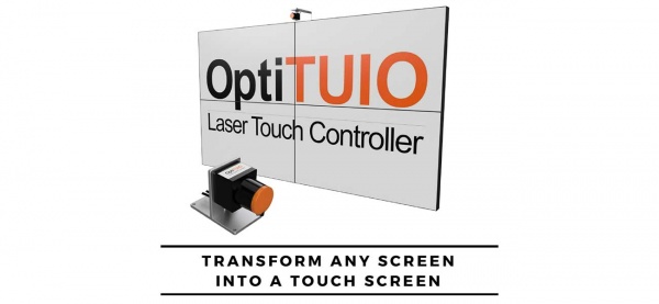
OptiTUIO™ is a tool to calibrate optical LIDAR sensor devices. With OptiTUIO™ it is possible to use laser contour scanners like the Leuze ROD4plus, Hokuyo sensors or the Sick LMS models for controlling any number of applications. OptiTUIO™ generates and detects unlimited touch points which then can be detected and processed by compatible applications and devices. OptiTUIO™ has 3 different output modes, TUIO, Mouse and Windows Touch.That means that any application which understands TUIO, Mouse or Windows Touch can get controlled with OptiTUIO™. With our solution you literally transform any flat surface into a multitouch surface.
Features
- Simplicity The software is very easy to use. The calibration process is finished after a few minutes. You can see what you are doing and the effect it has in realtime, so there is no need for time consuming switching between calibration and testing like in other solutions.
- Live preview You can see in realtime what you are doing. Our live preview shows you exactly where your sensor is placed and where your screen is placed. Fine-tuning is very easy to realize.
- Unlimited touch points We did not put any artificial limit on the number of simultaneous touch points.You can track as many as you want. The upper limit is a result of the angular resolution of the laser and the minimal object size that you set to detect.
- Many output methods Right now the software supports output to TUIO compatible devices over the network and to simulate Windows mouse and/or touch input to control a local Windows application. We also provide a separate application to perform gesture detection to control PowerPoint using swipes for example. Contact us if you need anything specific.
- Vendor independence Our software works with most of the common LIDAR sensors. This gives you the flexibility in choosing the device that fits best for your project and budget. Depending on which sensor you choose you can get up to 50 meters of detection radius with just one sensor. If there is a new sensor on the market we will try to implement it by request. See Section 3.3, “Supported LIDAR sensors” to find more.
- Multiple outputs Each output can be sent to one ore multiple different outputs. Giving you full flexibility in how to distribute them. You can also define multiple outputs to send the data of one device to many target machines, this is useful for cluster setups.
- Highly optimized detection algorithms We spent a long time building and analyzing statistics of the accuracy of the devices to optimize our filters to get the most accurate tracking possible. For each device we acquired millions of data points to get an accurate statistical analysis. This is why we are able to get a fully stable input without any jitter in the measurement. We took much care to keep the impact on latency minimal and you can tune the filter parameters yourself to get a different trade off between smoothness and latency.
- Multilingual User Interface To make it easier for any user to understand and use OptiTUIO. For now the following languages are available in the GUI (Graphical User Interface):
- English
- German
- Chinese
- French
- Arabic
- Portuguese
- Spanish
- Thai
We will translate the software into more languages if there is the need.
System and hardware requirements
Supported operating systems
- Mac OS X 10.11 El Capitan or newer
- Windows 7 or newer
- Ubuntu 16.04 Xenial Xerus or newer
- Debian 8 Jessie or newer
Hardware requirements
- A recent x86 or x86-64 CPU supporting SSSE3
- Intel starting from Core 2 and Atom
- AMD starting from Bobcat APU
- VIA starting from Nano
- At least 100 MiB of free HDD space
- At least 256 MiB of free RAM
- For the calibration software an OpenGL 2.0 compatible graphics card is required
Supported LIDAR sensors
- Hokuyo UST-10LX H01
- Hokuyo UST-10LX H01
- Hokuyo UST-10LX
- Hokuyo UST-20LX
- Hokuyo URG-04LX
- Hokuyo UTM-30LX
- Leuze ROD4 plus series
- Sick LMS 1xx series
- Sick LMS 5xx series
Please check this table for the features and specifications of the supported LIDAR sensors.
| Sensor | Hokuyo | Hokuyo | Hokuyo | Hokuyo | Hokuyo | Sick | Sick | Leuze |
|---|---|---|---|---|---|---|---|---|
| Model | UST-10LX H01 | UST-20LX H01 | UST-10LX | UST-20LX | URG-04LX UG04 | LMS 1xx | LMS 5xx | Leuze ROD4 plus |
| Accuracy | ±20mm | ±20mm | ±30mm | ±30mm | ±30mm | ±25mm | ±25mm | N.A. |
| Measuring area | 270° | 270° | 270° | 270° | 240° | 270° | 190° | 190° |
| Angular resolution | 0.125° | 0.125° | 0.25° | 0.25° | 0.36° | 0.25°/0.5° | 0.166°/1° | 0.36° |
| Scan rate | 40Hz | 40Hz | 40Hz | 40Hz | 10Hz | 25Hz/50Hz | 25Hz - 100Hz | 25Hz/50Hz |
| Scan Range | 10m | 20m | 10m | 20m | 3m | 20m | 30m | 15m |
| Connection | Ethernet | Ethernet | Ethernet | Ethernet | USB | Ethernet | Ethernet | Ethernet |
| Outdoor | No | No | No | No | No | Yes | Yes | Yes |
| Multi Echo Filter | No | No | No | No | No | Yes | Yes | Yes |
| Ambient light | 15000lx | 15000lx | 15000lx | 15000lx | 10000lx | 40000lx | 70000lx | Sunlight |
| Enclosure rating | IP65 | IP65 | IP65 | IP65 | none | IP65/IP67 | IP65/IP67 | IP65 |
| Basically any Hokuyo sensor which is supporting the SCIP 2.0 protocol should be working | ||||||

|
For the Hokuyo UST-10LX and UST-20LX, make sure that the device is running at least the 2.21 Firmware which can be obtained from the Hokuyo website. | |||||
|---|---|---|---|---|---|---|
Installation
Windows
On a windows machine there is no need to install OptiTUIO™. You will get a zip archive which contains the folders explained below. Then you just need to start the application with a double click.

|
Make sure that you install the Visual C++ runtime. You can find the vcredist_x64.exe in the OptiTUIO™ bin32 or bin64 folder.
If the Runtime is not installed OptiTUIO™ will not start. | |||||
|---|---|---|---|---|---|---|
Folders
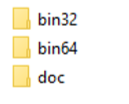
After you downloaded the latest OptiTUIO™ release you have to extract the archive first. In the extracted folder you can find the following folders:
- The bin32 folder holds the 32bit files.
- The bin64 folder holds the 64bit files.
- The docs folder holds software licensing information and the latest release notes in the CHANGES.html
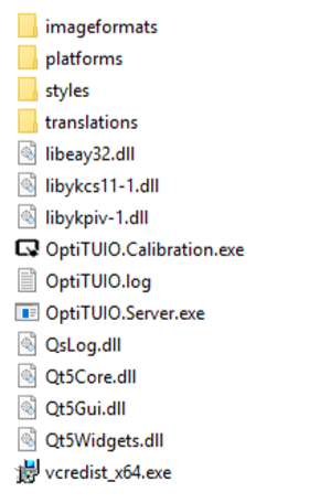
In the bin32 or bin64 folder you can find then the following files:
In this folder you can find the main OptiTUIO applications and the Visual C++ runtime:
- OptiTUIO.Calibration.exe (the main calibration application)
- OptiTUIO.Server.exe (the runtime / server application)
- vcredist_x64.exe (Visual C++ runtime)
Find more infos here how to [Autostart the server]
MacOS
Linux
Setup & Calibration
This chapter describes the whole process of the calibration with the OptiTUIO.Calibration.exe including how to install the license.
Quick Start
This is a short intro for a quick setup of OptiTUIO™:
- Connect the sensor to your machine and make sure that the machine can communicate with the sensor (Pingtest)

|
The sensor has to be in the same network as the machine which is running OptiTUIO™ | |||||
|---|---|---|---|---|---|---|
- Start OptiTUIO™ and Add your sensor in the Devices Tab
- Click the Info button to get the serial number of your device. Send this serial number to info@interactiveasia.com to receive your purchased license.
- Start the sensor with the Start button under the Devices tab. If the sensor scans correctly you can see the blue scan area in the sensor view.
- Add your screen and setup the dimensions of the screen
- Assign the screen to the sensor in the Devices tab und Screen in the Settings
- Add your desired output
- Now OptiTUIO™ is working and you should be able to get a touch feedback already depending on the output you defined.
First Start
Double click the OptiTUIO.Calibration.exe
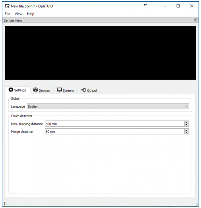
The Graphical User Interface of OptiTUIO™ will start
In the main menu you can find the typical menu entries:
- File - To load configuration files, save configuration files and exit the application
- View - To customize the preview window and open the Log window.
- Help - To install the license and view the license details.
- Language - Change the User Interface to your desired language
- Max. tracking distance - This value specifies from which distance to an existing touch point a new touch point is detected or if it is an existing one. Normal values are between 100mm - 400mm
- Merge distance - This value specifies the distance from which two touch points get merged together into one. Very helpful when applications are controlled with fingers on short distances, for example. Standard value is 40mm.
The GUI has the typical menu bar, the sensor view and the tab area.
In the menu bar you can load, safe and create new calibrations.
You also can adjust the view and under the Help menu you can install the license and get more information's about OptiTUIO™ and the license.
In the sensor view you will see the contour of the scanned area when the senor is scanning. In the tabs area you do the main calibration and adjustments.
In the bottom left corner you will see the scan frequency of the running sensor.
| Check the hardware specifications and Operating System requirements if you have any trouble to start OptiTUIO. Find this in Chapter 3. | ||||||
Read out the serial number of your sensor
To create your license we need to have the exact serial number of your sensor. You can read it out with OptiTUIO™. Click the Info button in the Devices tab. A popup will appear with your sensors unique serial number.
Install the license
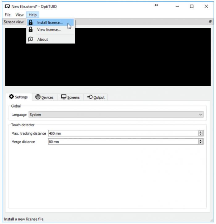
Until now (OptiTUIO™ Version 20190126_V1-2-3) our license system is based on a soft license. That means we will create a license file for you which you then have to assign in OptiTUIO™. The license file is bound to your sensors serial number. Means you can use the device license on any computer with the licensed sensor. If you have more then one sensor and also bought the license for all the sensors then we can create you a license file which contains all the licensed sensors. You can install the license file under the menu item Help -> Install license.
Additionally we offer a online demo license which can work with any connected sensor. Requirement for this is that the machine which runs OptiTUIO™ is connected to the internet.
After you successfully installed the license you can check under Help -> View License more details about your installed license.

|
The demo license is not for commercial use. It is for testing purpose only! | |||||
|---|---|---|---|---|---|---|
| You can install the license on any machine and Operating system which is supported by OptiTUIO. | ||||||
Add a sensor
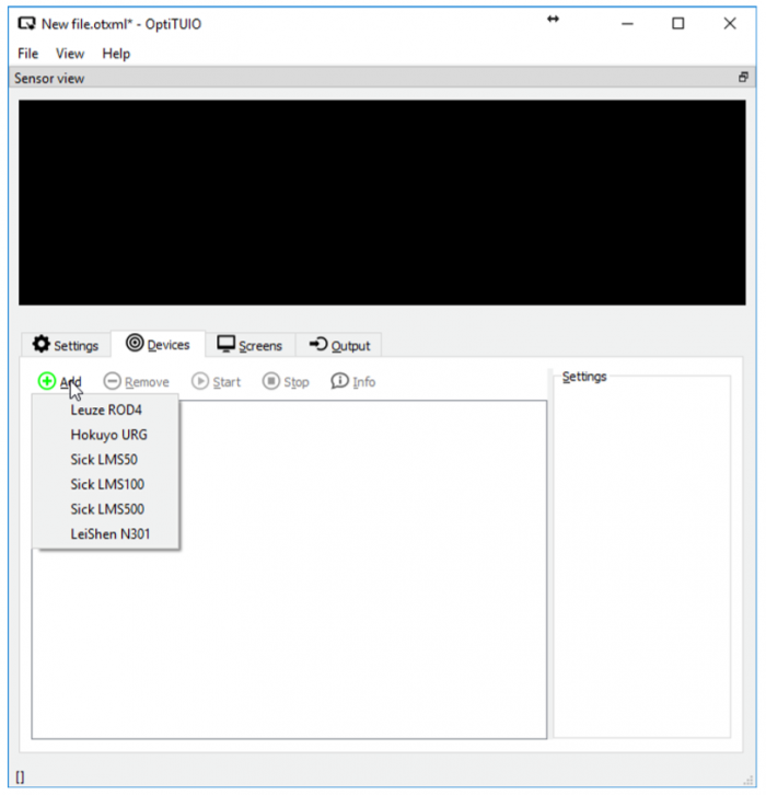
Add your sensor in the devices tab.
| The Hokuyo UST 10 LX, Hokuyo UST 20LX and the Hokuyo URG04 can be added via the Hokuyo URG item. This item includes all the Hokuyo sensors. | ||||||
Settings of the sensor
Here we describe the settings of a Hokuyo UST 10 LX sensor. The settings are very similar with other sensors.
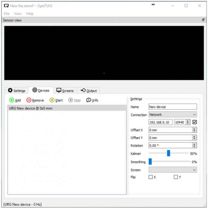
Once you added a sensor in the Devices tab the icons above the sensor list will be activated and the properties of the sensor will get available on the right side under the settings area.
This is the control panel to add, remove, start and stop the sensor.
- Add - this button opens the available sensor list where you can choose your sensor
- Remove - this button removes the selected sensor
- Start - Starts the sensor and the sensor will start scanning. If the sensor is runnig you can see the blue scanning area in the sensor view window
- Stop - Stops a running sensor and the sensor will stop scanning
- Info - This button shows you the serial number of the connected sensor. This button just works if the sensor is not running and connected correctly.
- Advanced - opens a new window where you can access [Advanced Setting]
| If you connected a sensor you can read out the serial number of the connected sensor via the Info button | ||||||
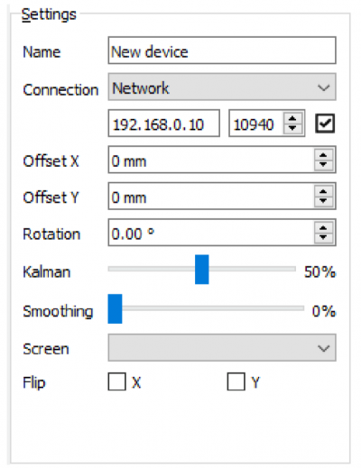
On the right side you have access to the settings of the specific sensor:
- Name - Here you can give your device a name
- Connection - By default the connection is set to Network. If you use the Hokuyo URG04 with a USB connection then you have to change this value to serial
- Offset X - Offset the sensor in X direction (left / right)
- Offset Y - Offset the sensor in Y direction (up / down
- Rotation - Adjust the Z rotation if your sensor is offset in Z direction
- Kahlman - Maximum deviation of the measured values to the actual distance. It is recommended to use the default values per device.
- Smoothing - This value will make the control smoother. But the higher the value is they more delay you will get.
- Screen - Here you have to assign the screen which you have created under the Screens tab.
- Flip x/y - Depending on the orientation of the sensor you can flip the values in X and Y

|
If you have not assigned the screen under the Devices tab you will not get any touch output | |||||
|---|---|---|---|---|---|---|
Advanced Settings
This feature is new since release OptiTUIO V1.2.3
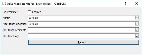
In this tab you have access to some advanced features.

|
This values are just exposed for our developers and some special cases. They should not be changed for normal usage | |||||
|---|---|---|---|---|---|---|
- Bilateral filter - For some special setups, especially when there are some error close to the sensor you can try to turn this option on. (default = off (unchecked))
- Margin - in some special cases you can adjust the margin that the touches are also recognized a bit outside of the actual touch area.
- Max. touch deviation - This is a very specific value and should not be changed!!!
- Min. touch segments - Defines how many rays have to recognize a object until its recognized as a touch point (default = 3)
- Min. touch age - The age of a touch point in frames before he gets sent to the output.
- Record button - Here you can record a file of the tracking process to send it to us for troubleshooting issues
Start the sensor
- Make sure that your sensor is connected correctly. You have to make sure that the computer which is running OptiTUIO™ is in the same sub network like the sensor.
- The Hokuyo UST 10LX has by default the IP address 192.168.0.10
- Make sure that your computer is in the same network or change the IP address of the sensor to your desired IP address.
- If you are able to ping the sensor via ping 192.168.0.10 then OptiTUIO™ will be able to connect to the sensor too.
- You can ping the sensor if you open a cmd window in Windows
Windows Key + r. Then typecmdin the Run Window and press Enter. - In the command window type
ping 192.168.0.10or the correct IP address of your sensor. - If you get a positive feedback from the sensor OptiTUIO™ will be able to connect to the sensor.
- You can ping the sensor if you open a cmd window in Windows
- Select the sensor in the Devices tab and click Start in the control panel.
- Once the sensor is started you can see the blue scan area in the sensor view.
- In the bottom left corner of the GUI you can also see the scanning frequency of the sensor.
| Make sure that your network configurations are setup correctly. Find more info's here Hardware / Networking | ||||||
Setup the screen
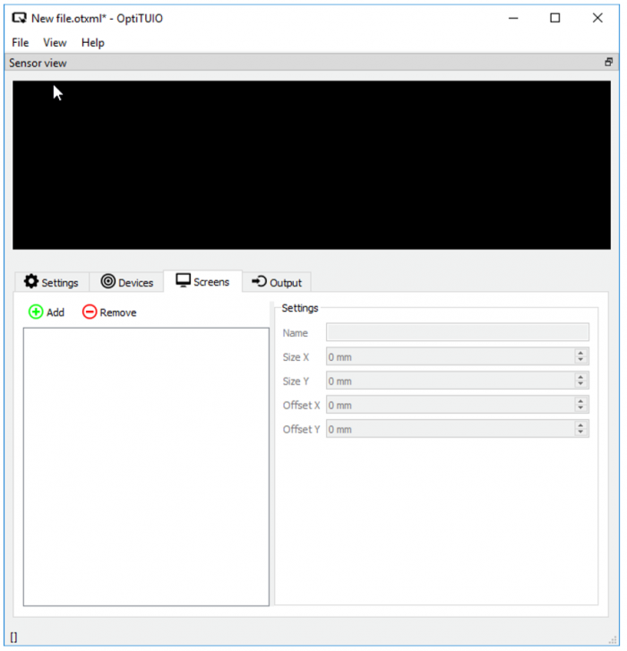
Click the Screens tab and then the Add button to add a new screen. Then setup the Size X (width) and the Size Y (height) of the screen in millimeters.
- Name - Setup a name for your screen
- Size X - The width of the physical touch screen area in mm
- Size Y - The height of the physical touch screen area in mm
- Offset X - offset the screen left or right in relation to your device
- Offset Y - offset the screen up or down in relation to your device
Setup the output
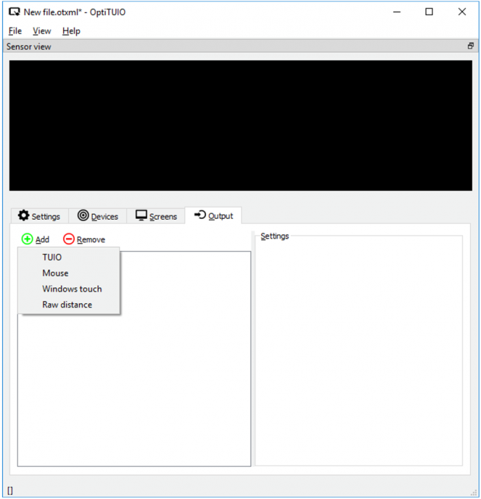
In the Output tab you can setup your desired output. OptiTUIO supports TUIO, Windows Touch and Mouse control.
Select your desired output
- TUIO - This will setup an TUIO output which then will directly send TUIO informations to the specified address and port.
- Mouse - This will simply control the computer mouse
- Windows touch - With this output you can simply control Windows touch
- Raw distance - This is a special output which sends RAW distance values to a specific OSC address
TUIO output
TUIO is a network protocol designed for transmitting MultiTouch input data. It is the de-facto standard for receiving information from MultiTouch devices. Any application which understands TUIO will be able to communicate directly with this output. Typical applications are Ventuz, Unity, VizRT, UE4 and many other media servers or playout applications.
The following list describes the settings of the TUIO output.
- Name - Here you can assign a name for your output
- Host - The machine where OptiTUIO™ will send the TUIO informations (default: localhost / 127.0.0.1)
- Port - The port on the host machine where OptiTUIO™ will send the TUIO informations (default: 3333)
- Screen - If you have more then one screen then you can define from which screen the TUIO information's will come (default: All)
Mouse output
The mouse is the primary input device used to interact with objects in Windows, Linux and MacOS. This output will simply control your mouse pointer. There are two different control options with the windows mouse.
The following list describes the settings of the Mouse output.
- Name - Here you can assign a name for your output
- Offset X - Here you can offset your mouse pointer in X direction.
- Offset Y - Here you can offset your mouse pointer in Y direction.
- Size X - This value is set automatically if you start OptiTUIO™. It is the width in pixel of the screens you have connected to your computer. You can change this values if you just want to control one screen.
- Size Y - This value is set automatically if you start OptiTUIO™. It is the height in pixel of the screen you have connected to your computer.
- Screen - If you have more then one screen then you can define from which screen the Mouse information's will come (default: All)
- Mode - Simple and Two click.
- The simple mode uses the first touch point and moves the mouse directly to that position and executes a left click.
- The two click mode uses the first touch point to move the mouse pointer without any click action. If you hold your first finger in the screen then you can create a Left click if you touch with your other hand left side of the first hand. Or a right click if you touch right side of your first hand which controls the point.
| The mouse just can be controlled with one touch point. Or in the two click mode with maximum two touch points. There is no way to control two mouse pointers with one OS. | ||||||
Windows touch output
New hardware and API elements in the Windows 7 operating system provide applications the ability to receive input from multiple contacts. This gives such applications the ability to detect and respond to multiple simultaneous touch points on the application's visible surface. This output of OptiTUIO™simply gives you the ability to control your computer via Windows touch. Please find more information's on the Windows website: About the multi touch SDK
The following list describes the settings of the Windows touch output
- Name - Here you can assign a name for your output
- Offset X - Here you can offset your mouse pointer in X direction.
- Offset Y - Here you can offset your mouse pointer in Y direction.
- Size X - This value is set automatically if you start OptiTUIO™. It is the width in pixel of the screens you have connected to your computer. You can change this values if you jaust want to control one screen.
- Size Y - This value is set automatically if you start OptiTUIO™. It is the height in pixel of the screen you have connected to your computer.
- Pressure -
- Radius -
- Screen - If you have more then one screen then you can define from which screen the Windows touch information's will come (default: All)
RAW distance
This is a special output which is used to send raw data of the sensor to a specific OSC address.
The following list describes the settings of the RAW data output
- Name - Here you can assign a name for your output
- Host - The machine where OptiTUIO™ will send the RAW data information's (default: localhost / 127.0.0.1)
- Port - The port on the host machine where OptiTUIO™ will send the RAW data information's (default: 7000)
- Address - The OSC address where OptiTUIO™ will send the information's.
Saving your configuration
When you are finished with the calibration and you are satisfied go to the Menus -> File -> Save as.
Save the .otxml file at a place where you can find it later. This file can also be opened by a text editor to change values manually.
Run the server application
After you successfully calibrated your sensor you can close OptiTUIO.calibration.exe and start the OptiTUIO.Server.exe!
The server application will ask you which config file the server should start. Choose your .otxml calibration file and the server will start tracking directly.
Autostart the server
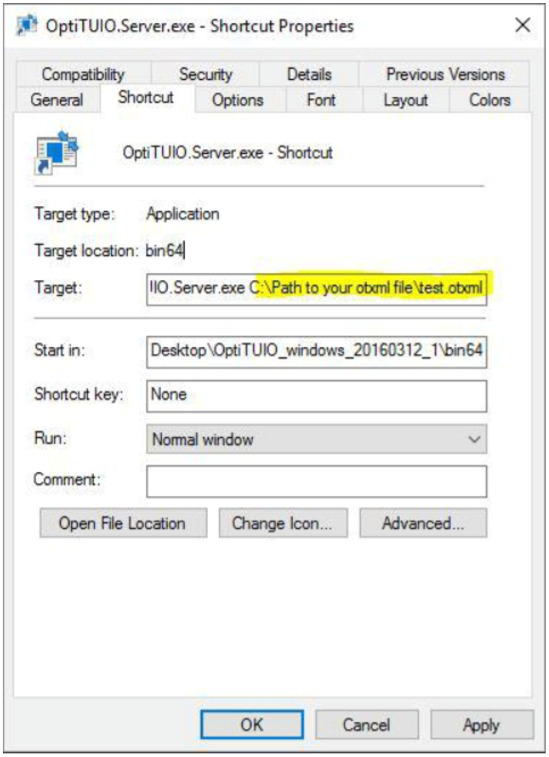
If you want that OptiTUIO™ always starts automatically when the system is starting following the description below:
- Create a shortcut of the OptiTUIO.Server.exe somewhere on your machine.
- Open the Properties file dialogue (Right click to the shortcut and click Properties on the bottom of the dialogue menu) of the shortcut and paste the path to your configuration file *.otxml at the end of the Target path. (See picture below)
- Now you can put this shortcut to the autostart folder in Windows.
- The autostart folder you can find here:
C:\ProgramData\Microsoft\Windows\Start Menu\Programs\StartUp
- The autostart folder you can find here:
Licensing
Device / offline license
The Device or Offline license is the commercial non free license. This license is bound to a sensors serial number. We also can create a license which is licensed for mor then one sensor in one license file.
Demo / online license
The demo license is for testing purpose only. We activate this license for a maximum of 24 hours. The demo license is just working if your machine has a internet connection.
FAQ
OptiTUIO is not starting
Make sure that you have the latest Visual C++ runtime installed. You can find the installer in the OptiTUIO folders. The filename is vcredist_x64.exe
OptiTUIO is not starting the user interface
Delete the license.otlic file in the C:\Users\yourusername\AppData\Roaming\OptiTUIO folder and start OptiTUIO again. After that install the license again.
Make sure that you run the latest version of OptiTUIO.
File location for the installed license file
OptiTUIO stores the installed license file in the following folder %APPDATA%\OptiTUIO
Please contact us via email at info@interactive-asia.com
